Coordinate Measuring Machines, or CMMs, use coordinate technology to measure geometry along the X, Y, and Z axes. The earliest CMMs, developed by Ferranti Company in the 1960s, were 2-axis models that became 3-axis systems for better measuring capabilities.
Even a 0.001 mm fluctuation may affect performance in aerospace and automotive, which renders CMM measurement vital. CMMs now use synthetic ruby probes, probing technologies, and software for great precision. To preserve measurement integrity, efficiency, waste reduction, and expensive production oversights, CMM calibration must be done periodically.
Components of a CMM
Machine Frame
The machine frame provides stiffness and stability during CMM measurement. It is made of granite or aluminum, depending on its qualities. Granite’s vibration-dampening properties decrease external vibration-related measurement inaccuracies. Aluminum frames are lightweight yet, thanks to improved engineering, provide stiffness and thermal stability. For accurate frame design, thermal expansion coefficients must be considered. For example, a carbon fiber composite frame may limit thermal expansion and preserve accuracy in variable temperatures.
Probing System
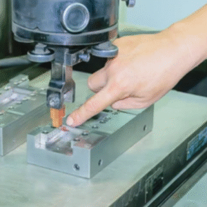
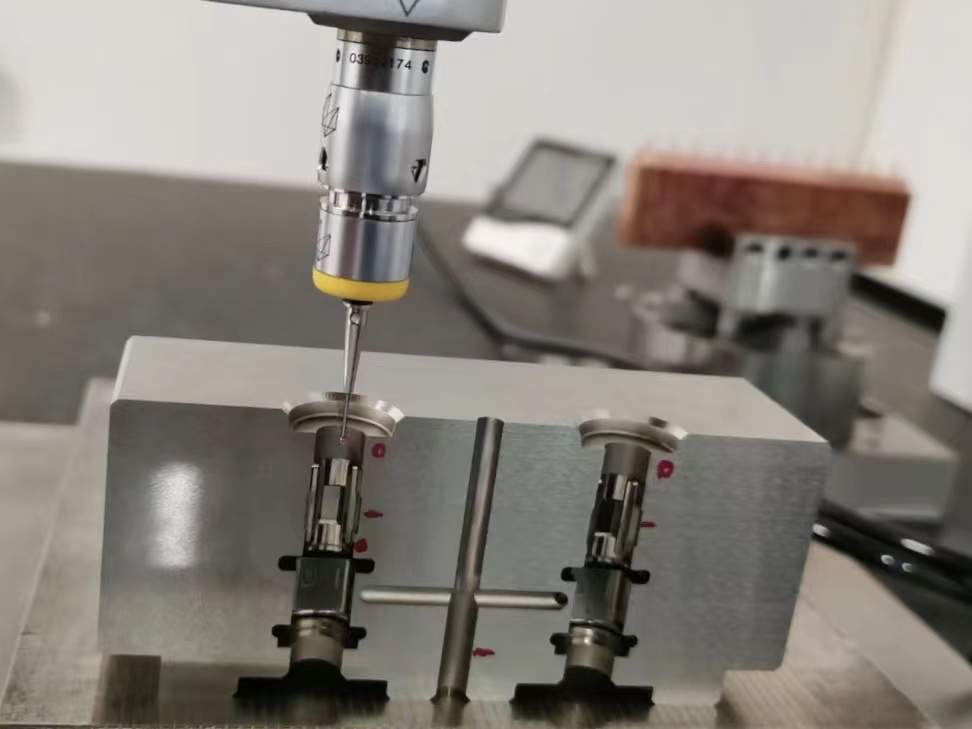
CMM measurement relies on touch probes, optical sensors, and laser scanners. Touch probes are precise within micrometers since they employ a stylus to touch the component. Cameras or photogrammetry provide non-contact measurements of sensitive surfaces using optical probes. High precision occurs using laser probes to quickly scan convoluted geometries. Hard and wear-resistant probe materials (ruby or silicon nitride) provide lifetime and accurate measurement.
Drive Framework
The drive framework controls probing system movement along the X, Y, and Z axes for exact CMM measurement. It may be manual, automatic, or both, employing linear motors for uniform, precise motion. Air bearings in high-precision CMMs optimize friction and movement for greater measurement accuracy. The framework must prevent deflection under load, so FEA helps design rigid, high-performance components. Systems may employ laser interferometer feedback loops to adjust the location in real-time with nanoscale accuracy.
Controller
The controller interprets probing system data and controls precise motions during CMM measurement. Current controllers use DSP to calculate confusing geometrical equations and correct for thermal drift and machine dynamics. Their sub-micron control accuracy gives detailed measurements. They feature multi-sensor integration for easy touch, optical, and laser probe switching. It suits applications that need many measuring techniques in one inspection cycle.
Software
Data analysis, measurement routine programming, and reporting need CMM measurement software. Leading software includes CAD model integration, real-time error correction, and SPC. Ongoing inspections are guaranteed by these programs’ automated measurement pathways from CAD data. For example, PC-DMIS can laser scan and provide surface analysis and deviation data. AI and ML techniques help the software rectify errors for better measuring reliability.
Uses of CMM
Quality Control
Quality control relies on CMM measurement for production accuracy and uniformity. Such tools can identify minor design changes and give feedback for better manufacturing. E.g., CMMs measure engine blocks and transmission parts for tolerances in the automobile sector. This lowers faults for greater product dependability. CMMs also automate inspections to decrease human error and time. Real-time data collecting enables fast modifications for continual quality improvement. CMMs help quality control fulfill ISO 9001’s demanding inspection requirements.
Dimensional Inspection
CMM measurement validates component dimensions versus design blueprints. CMMs measure convoluted geometry using up-to-date probing techniques. For instance, CMMs help inspect aircraft components with complicated forms and tolerances for precise requirements. They measure dimensions to micrometers for maximum accuracy. CMMs also provide detailed reports on deviations from nominal dimensions. It helps diagnose and fix production difficulties. CMMs expedite inspection operations and boost measurement repeatability.
Reverse Engineering
Many reverse engineering programs use CMM measurement to replicate component designs. CMMs can measure physical items without design documents. For example, CMM data can represent manufacturing legacy components without CAD models. Scan the component to create a point cloud, which is turned into a 3D CAD model. It may be copied or modified. CMMs may also measure fine minutiae that other methods overlook for a complete digital depiction. Such capability may benefit aerospace and defense, which need exact part reproduction.
Statistical Process Control (SPC)
SPC uses CMM measurement to regulate production operations. CMMs discover trends and variances while measuring at many manufacturing phases. E.g., they may identify process changes in high-volume manufacturing by measuring part dimensions. SPC analysis requires mean and standard deviation calculated from such observations. It guarantees process stability and capacity. CMMs may also communicate with SPC software for real-time feedback and corrections. A more regulated and predictable production process cuts scrap and boosts product quality.
Instrument Alignment
CMM measurement accuracy aids instrument alignment. CMMs precisely place essential equipment parts, including turbine shafts and robotic arms. In assembling massive industrial equipment, CMMs may monitor component alignment to within microns for maximum performance. Misalignment may cause equipment failure, wear, and inefficiency. CMMs give data to position components to fulfill alignment specs. Remember, precision is key to aircraft, automotive, and heavy equipment, where alignment affects safety and operation.
Verifying Geometric Dimensioning & Tolerancing (GD&T)
GD&T specification verification calls for CMM measurement. Part form, orientation, and location are allowed under GD&T. Precision CMMs assess these qualities so components meet design intent. For instance, medical device manufacturing requires strict GD&T standards, and CMMs check that each item fits tolerances. Machines can measure complicated geometries and feature relationships for complete validation. Furthermore, CMMs can automatically translate GD&T symbols and use the right measuring methods to minimize human error. Subsequently, it strengthens product reliability to fulfill customer and regulatory requirements.
Importance of CMM Calibration
CMM calibration helps preserve accurate CMM measurement capabilities while addressing flaws in the machine’s 21 planes. Periodic calibration improves measurement accuracy for less waste and material use. Perfect-looking items are calibrated to eliminate manufacturing delays and undiscovered faults. Furthermore, calibration avoids failures by fixing small issues before they stop production, saving firms thousands of dollars each hour. Similarly, uncalibrated CMMs may cause product recalls to hurt consumer confidence and legal liability.
In aerospace and medical device manufacturing, calibrated CMMs verify the integrity of complex components for high-quality output. Industrial accreditations, including ISO 9001, require calibration management processes for competitive parity and customer trust, rendering CMM calibration vital. Remember, critical calibration stages include post-upgrade scenarios, where new hardware or software may alter measurement dimensions; post-repair, where even minor adjustments can affect accuracy; after significant movements or inactivity, as environmental changes impact precision; and regular intervals to counteract wear and tear.
Need expert solutions regarding CMM measurement or CMM calibration? Contact ShanenTech.